This is a record of a project started last October to make it easier for my grandson to use his train set. First of all, the problem: Ben is 7 1/2. He has his own room but also has a 5 year old sister and 2 1/2 year old brother. Last Christmas (2010) he was given a Hornby Railroad Circus train set. For most of the year it languished in its box because the only way to play with it was to set it up on the carpet in his bedroom, where it competed for space with other toys and got interfered with by brother and sister.
Grandad to the rescue! I decided to make a baseboard for it with the track permanently set up so he could play with it properly. As soon as I started to work out sizes I realised two things: that the track was too simple to keep his interest for any length of time (an oval of Hornby radius 3 track with one point and a curved siding); and that if the baseboard was to be capable of being tidied away it needed to be in two halves. Leaving it set up permanently isn't really an option.
After some online research and buying a book or two I decided to make the two halves from a sheet of ply on a lightweight subframe. The ply sheet was too big for my car so I had to saw it in half in Wickes' carpark, which was fun in a not fun at all kind of way. Once home I made two sheets each 1m by 1.2m so the finished layout would be 2m by 1.2m. The subframe is made from 1" by 1.5" nominal which I chopsawed into accurate lengths in order to use glued and screwed butt joints. I drilled holes in all the internal members to allow for later wiring.
At this point the project was put on involuntary enforced hold. An emergency appendectomy slows you up quite a bit!
After a few weeks I was able to assemble the subframe and boards, using screwed and glued construction throughout. The result is light enough for an adult to lift and manouver about while being stiff and solid enough to be a long-term baseboard. The two halves of the baseboard have 3 cabinet-makers' dowels fitted for alignment and clasps on either side to make sure the halves are pulled together. I have also rounded over all external edges and corners using a 1/4" router bit so there's less chance of anyone hurting themselves by running into a corner.
While I was unable to work on the baseboard I researched layouts and how to wire them, mostly online. Two resources in particular helped me a lot: Brian Lambert's Hints and Tips and the resources at New Railway Modellers, which is far more than an online shop. I realised that for there to be longer-term play value the layout needed to be extended. At this stage I discovered XTrkCAD, a very useful program indeed and one I recommend highly. I loaded the HO layout templates and set to work. The final design (for now) has two ovals with points to allow switching between them and back again - two sets of face to face points on opposite sides of the layout; an external siding reached from the outer oval and a long branch line or siding reached from the inner oval.
I needed to make sure that the points are positioned away from the board joint and not over the baseboard struts, so there will be room for the motors. I've tried to avoid cutting track and have used short track pieces at the joining edges in most cases. One straight will need a diagonal cut but that can't be avoided.
I decided to paint the baseboard rather than using flock or mats partly because of the inevitable wear and tear and also because of the additional costs involved. The extra track to make the new layout has already cost more than the original trainset! I originally though about using matt emulsion household paints that I already had, tinted using children's poster paints from ELC. After some experimenting I found you need a lot of poster paint to make any difference to the emulsion, so I bought some 100ml test pots from our local independent DIY store - not the pre-mixed tiny containers but small proper tins.
I used the computer to plan out the road positions and trackbeds and then set to work with the paints and a decorators' sponge torn in pieces. The trackbed was first painted in a plain grey and the ground in a plain pale green, both of which paints I already had. Then the trackbed was sponged over with my home-tinted paint in a dark reddish purple. The roads were laid out using masking tape and pencil lines and painted in a dark grey. When that was dry and the tape removed I went to work with the sponging colours for the land. Mostly a reddish brown to represent mud and soil, a bright grass green and a yellow to add the impression of little flowers.
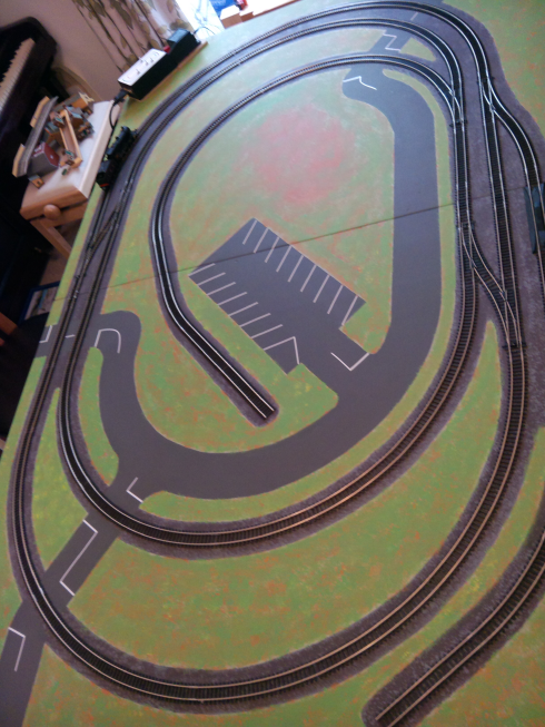
To make the roads and car park more realistic I added some white lines, using thin vinyl self-adhesive strips. The entire layout looks as shown here - picture taken at an odd angle which I will replace soon!
Partly because it is a train set and not a model railway, but mostly because of the need to allow it to be stacked against the wall when not in use, there will be no permanent buildings or trackside furniture. If Ben decides later to turn it into a model railway, they can be added then. However I did buy and make some card kit buildings - a station and a goods shed.
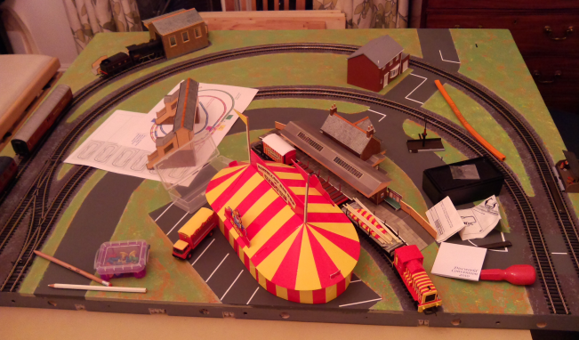
This picture shows quite a few of these components on half the baseboard where I put them while I worked on the other half!
The board is too big to allow manual working of at least half the points, so I decided to motorise them all while I was about it. I bought a couple of Horby points motors and switches, then realised there were better alternative so bought some Seep motors and small return to centre silver switches - see the section on the control unit below.
The next big adventure was to lay and wire the track and points. I was faced with some interesting design decisions on how best to connect the two haves of the baseboard and also how to connect the switches and controller without having them permanently on the board, which would go against making the boards stackable. The train set is DC rather than DCC and that seems better from the point of view of keeping things simple.
To make the connections between the two boards I used Expo Tools' 8mm 12w Pluggable Terminal Blocks. These are like a pair of normal connector strips but one side has a protruding plug that fits into the other side of each connector. When fitted to the mating edges of the two baseboards then when the boards are joined the circuits are automatically be joined up too, with no further plugging in required. Although it would also be possible to use the same technique to connect a panel holding the controller and switches to the baseboard, so that placing the control panel in place would automatically make the correct circuits, I found a better way.
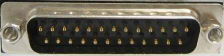
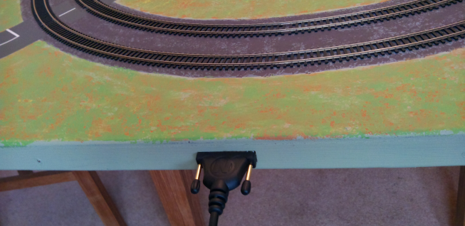
I used a 25-way D-sub connection for the control station. This has more connections than I needed, but means there's scope for expansion. I fitted a male socket to the edge of the baseboard and a female to the control unit, and bought a 3m connecting cable. This way round it means that little fingers won't accidentally touch even a 12-volt supply, and the control unit can be positioned anywhere within 3m of the board.
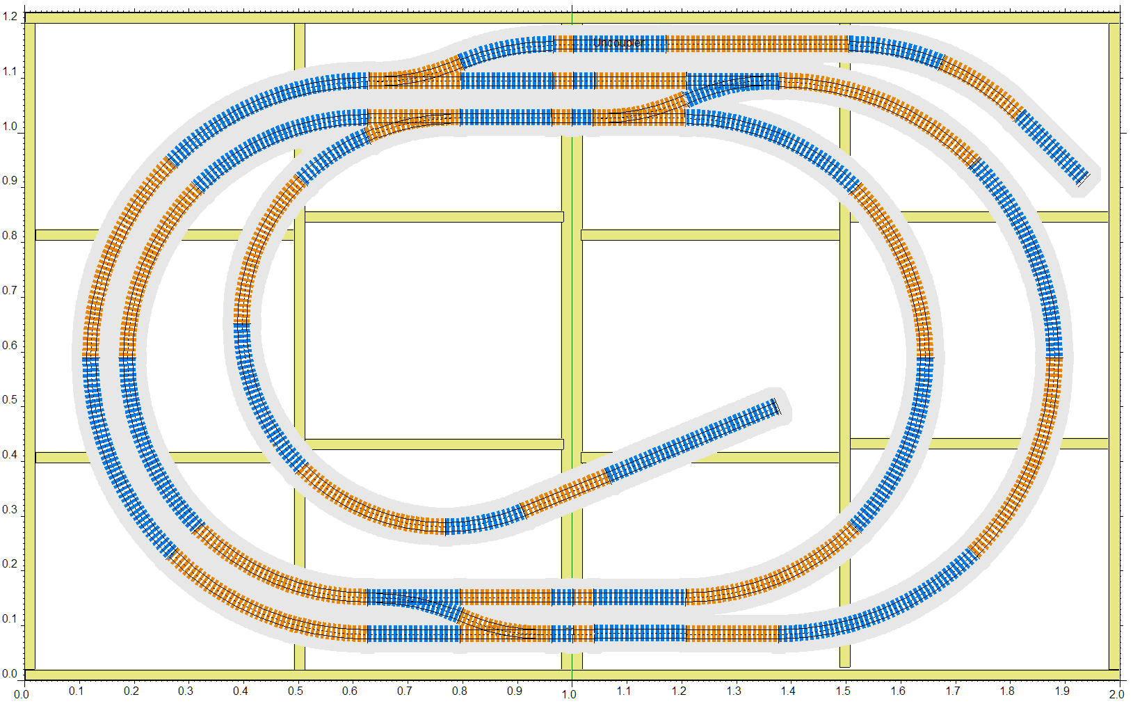
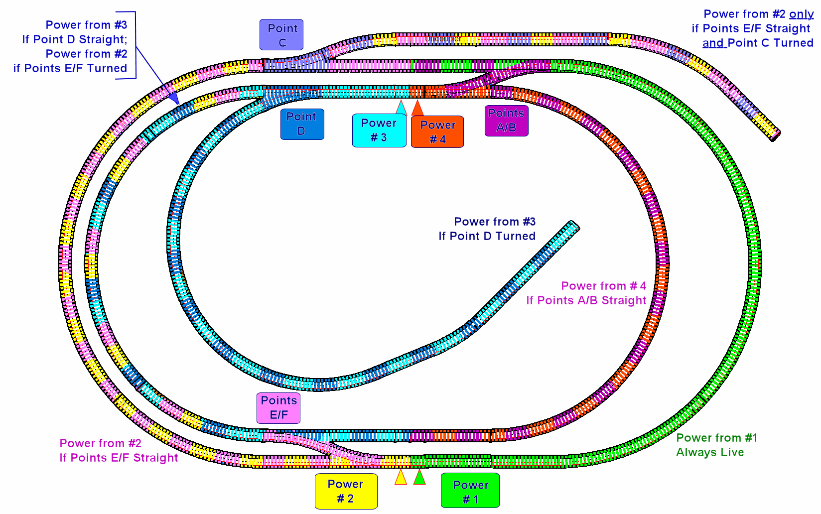
The underboard wiring was straightforward once I had worked out where the connections should go and what the power zones should be. This illustration shows the track schematic with colour-coded segments that depend on the position of the power inputs to the track and which way the points are set.
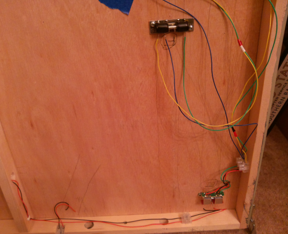
The picture below shows a couple of point motors and some power wires underneath the board. This was before I had tidied up the wires and while it was still a work in progress.
I decided to double-gang the points that form crossovers in order to simplify the operation. This meant that pair of points A and B, and also the pair E and F, are each operated by a single switch. I hit problems - the point motors didn't always work or when they did they made a buzzing noise. A bit of research (that I should have done earlier!) identified that the controller wires I thought gave DC current in fact give AC, and that you really neeed something called a Capacitor Discharge Unit (CDU) in between the AC terminals and the switches.
A CDU costs about a tenner and I got one from the internet, wired it in (inside the controller unit - see below) and it all worked properly! Well, nearly ... one point refused to switch in one direction. This was due to a loose wire which took a bit of ingenuity to find, as the point is on the 'slave' baseboard and all the rest of the wiring is under the 'master' board. Once fixed the points all worked perfectly. Yay!
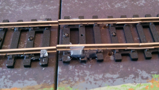
Another snag was due to the way I fitted the power leads to the small track pieces next to the join. One of these came to pieces and I had tried to fettle it with a hot glue gun. The resulting mess looked like this:
I removed the piece, which fell apart in my hands. The power wires were OK though:

I carefully cut a new piece using my Dremel, soldered the power wires to it and fitted it in place. Looks a lot neater and works perfectly.
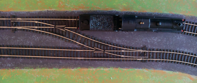
Another snag is that my second-hand engine (see top of page) stops at slow speeds when it goes through the points. If a little pressure is put on the cab, it starts again. It seems that the engine weight distribution needs modifying but I'm not yet sure how to do it.
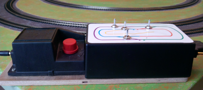
I wanted to have a control console that lets Ben control the trains and the points from one place, without lots of wires to be connected up beforehand. The contoller that comes with the train set has a speed dial, a direction switch and a couple of (AC power) terminals for accessories. I decided to take a Maplins plastic box, sold for electronics projects, and modify it so that it fits over the Hornby controller and gives a layout map with the points switches on it. All the complicated wiring, including the CDU to make the points operate smoothly, fits inside out of sight. The input wire from the transformer plugs into one end and the connecting D-sub_25 cable plugs into the other end and into the layout frame.
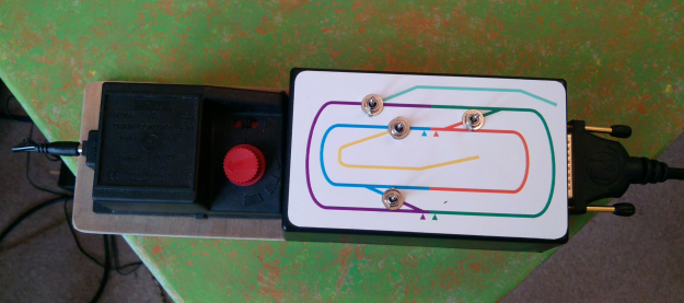
The Maplins box is about 6" x 4" so I printed the layout map onto good quality photo card and glued it to the box after first drilling mounting holes for the switches. When the glue was dry I used a craft knife to cut throught the photo card and mounted the switches. The result looks pretty good. The layout map shows the power sections of the layout in different colours, to make it easier to see which sections will be powered for each points setting
The finished control unit
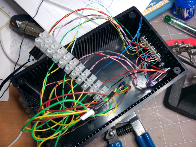
The wiring inside the box, while it was being connected up. The multi-coloured wires come from an old d-sub-25 cable that I cannabalised. It ended up a bit neater than this!
In my 60s, married with 3 daughters, 4 grandchildren and a Border Collie. I had a Triang train set as a boy, which I remember adapting to carry my pet mice aound in the carriages, but never a model railway as such. This is my first such project and I'm finding it challenging and fascinating. It is very possible that when its finished I'll start investigating making my own - if I do it will be N gauge and DCC. TIme to start negotiating with my wife!